 Japan
Japan  United States
  Mexico
  Brazil
  EU
EU  United Kingdom
  Germany
  Spain
Spain  France
  Italy
Italy  Poland
  Turkey
  Czechia
  China
China  Asia Pacific
  Vietnam
  Indonesia
  India
India ![]() For steels
For steels
![]() For stainless steels
For stainless steels
![]() For cast iron
For cast iron
![]() For non-ferrous metal
For non-ferrous metal
![]() For difficult to cut material
For difficult to cut material
![]() For hardened material
For hardened material

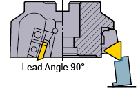
Lead Angle 90°
Back force is in the minus direction. Lifts the workpiece when workpiece clamp rigidity is low.
Lead angle 75° is recommended for face milling of workpieces with low rigidity such as thin workpieces.

The largest back force.
Bends thin workpieces and lowers cutting accuracy.
* Prevents workpiece edge chipping when cast iron cutting.

* Principal force : Force is in the opposite direction of face milling rotation.
* Back force : Force that pushes in the axial direction.
* Feed force : Force is in the feed direction and is caused by table feed.
When the depth of cut and feed per tooth, fz, are fixed, the smaller the lead angle (KAPR) is, then the thinner the chip thickness (h) becomes (for a 45° KAPR, it is approx. 75% that of a 90° KAPR). This can be seen in below. Therefore as the KAPR increases, the cutting resistance decreases resulting in longer tool life. Note however, if the chip thickness is too large then the cutting resistance can increase leading to vibrations and shortened tool life.

Below shows wear patterns for different lead angles. When comparing crater wear for 90° and 45° lead angles, it can be clearly seen that the ctater wear for 90° lead angle is larger.
