 Japan
Japan United States
 Czechia
 United Kingdom
 Germany
 Spain
Spain France
 Italy
Italy Poland
 China
China South East Asia, Oceania, South Africa
 India
India![]() For steels
For steels
![]() For stainless steels
For stainless steels
![]() For cast iron
For cast iron
![]() For non-ferrous metal
For non-ferrous metal
![]() For difficult to cut material
For difficult to cut material
![]() For hardened material
For hardened material
Turning Tools
Turning Holder
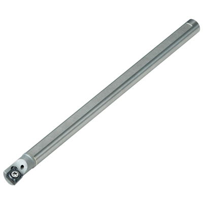
Boring
SS_SCLC_E


※Actual products and images (representative examples) may differ. Please check the dimensions column in the table below for details.
EDP No:22979513
| Shape | EDP | Order Number | Stock | Category | Bundled quantity | |||||||||||||||||||||||||||||||||||||||||||||||||||||||||||||||||||||||||||||||||||||||||||||
|---|---|---|---|---|---|---|---|---|---|---|---|---|---|---|---|---|---|---|---|---|---|---|---|---|---|---|---|---|---|---|---|---|---|---|---|---|---|---|---|---|---|---|---|---|---|---|---|---|---|---|---|---|---|---|---|---|---|---|---|---|---|---|---|---|---|---|---|---|---|---|---|---|---|---|---|---|---|---|---|---|---|---|---|---|---|---|---|---|---|---|---|---|---|---|---|---|---|---|
Stock:
![]() :Inventory maintained.
:Inventory maintained.
![]() :Non stock, produced to order only.
:Non stock, produced to order only.
![]() :Inventory maintained. To be replaced by new products.
:Inventory maintained. To be replaced by new products.
![]() :Inventory maintained in Japan.
:Inventory maintained in Japan.
Symbol Description
Tool Material
Tolerances
Angle, Coolant hole, Sharp corner edge and Gash land
Coating